
The three standard sprinkler piping layouts defined by NFPA 13 are tree (dead-end), looped, and gridded. Use a tree layout for small, simple systems where pressure is adequate and hand calculations are practical. Choose a looped arrangement when you need a second flow path without the full complexity of a networked grid. Go gridded when hydraulic efficiency is the priority — large warehouses, long remote-area runs, or tight supply constraints where every psi counts.
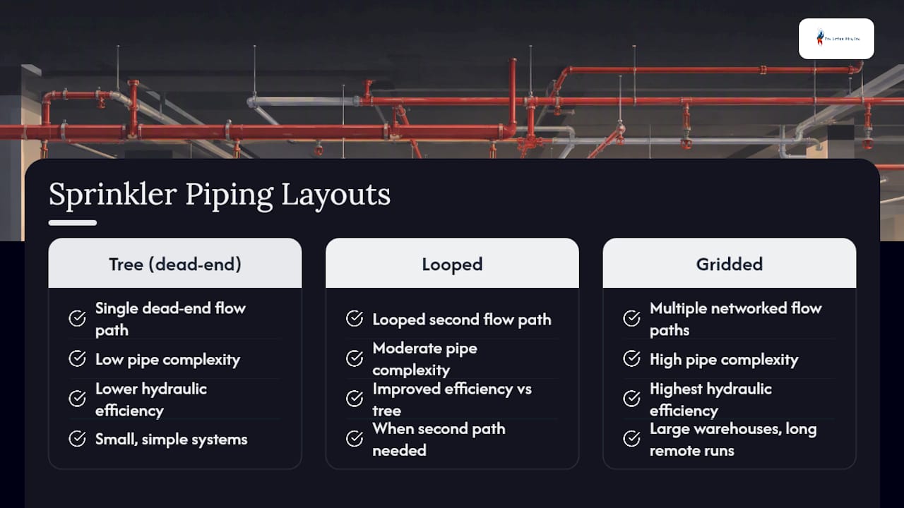
MeyerFire confirms that the right choice depends heavily on building type and water-supply constraints, and AXA XL Risk Consulting adds that gridded systems permit smaller pipe sizes or longer distances from the supply — but only when the iterative hydraulic balancing is done correctly. The sections below break down each layout, the code constraints that govern them, and a prioritized decision checklist you can use at concept design.
Key Takeaways
The right sprinkler piping layout depends on water supply, remote-area distance, system operation type, and occupancy hazard — and NFPA 13 requires hydraulic verification of the most demanding area for every gridded design.
| Point | Details |
|---|---|
| Tree layout: small systems | Use for simple, small occupancies where pressure is adequate and hand calculations are practical. |
| Looped layout: medium complexity | Choose when a second flow path reduces friction loss without requiring full grid modeling. |
| Gridded layout: large or demanding | Best for large warehouses and long remote runs; requires computer hydraulic modeling. |
| Dry and double-interlock preaction | Gridded layouts are prohibited; tree or looped only per NFPA 13. |
| Preactionfire for Denver projects | NICET-certified technicians provide layout consultation, hydraulic modeling, and NFPA-compliant installation in the Denver Metro Area. |
Table of Contents
- What are the three types of sprinkler layouts?
- How do system operation types restrict layout choices?
- What calculation method does each layout require?
- How do you choose the right sprinkler layout for your project?
- Hybrid arrangements and retrofit considerations
- A practicing designer’s perspective on layout selection
- Preactionfire’s layout design and installation services in Denver
- Sources
What are the three types of sprinkler layouts?
Tree (dead-end) layout
A tree layout feeds sprinklers through a single path: water travels from the riser to a cross main, then out through branch lines that terminate at a dead end. Nothing loops back. The schematic looks exactly like a tree — one trunk feeding progressively smaller branches, with no return connections.
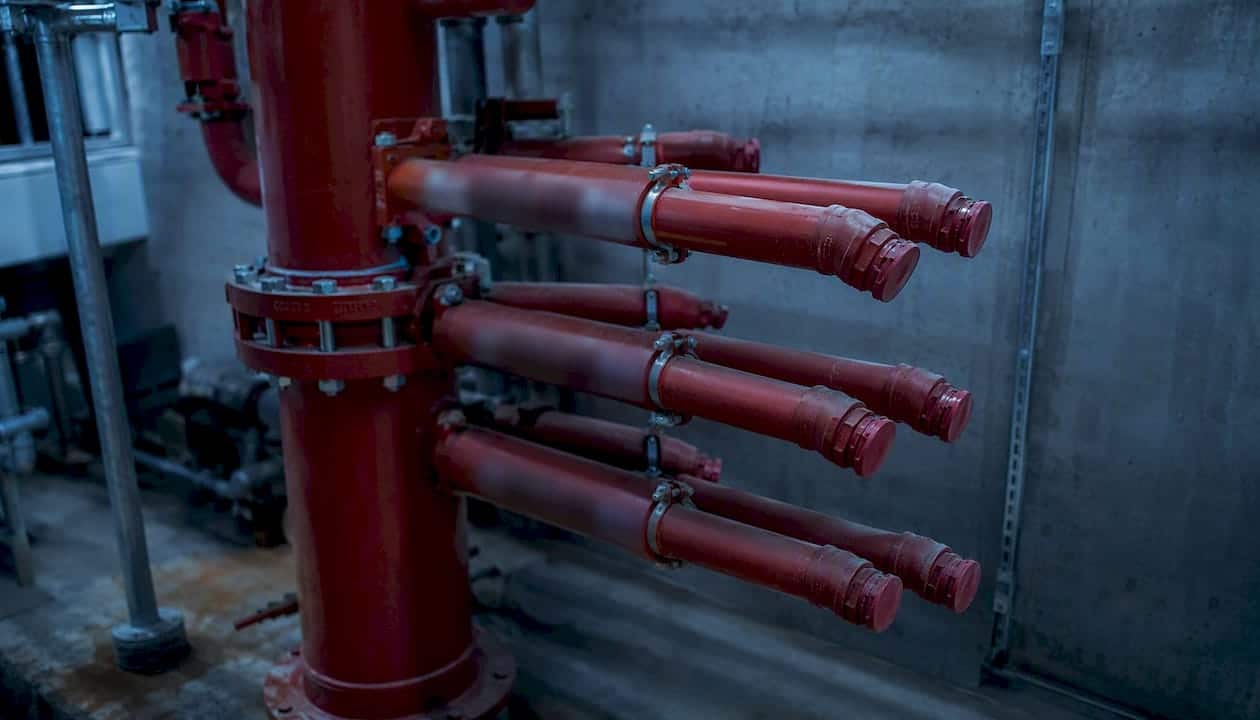
This is the right call for small systems: a single-story retail space under a few thousand square feet, a small mechanical room, or any occupancy where the available pressure comfortably covers the remote-area demand without requiring pipe-size optimization. Because water has only one path to any sprinkler, the hydraulic demand at the supply is higher than for looped or gridded arrangements of the same size. That said, the pipe-schedule method works cleanly with tree layouts, and a competent designer can verify the hydraulics by hand without specialized software.
Installation cost tends to be lower than the alternatives, due to less pipe, fewer fittings, and straightforward routing that reduce labor hours. The trade-off is that any blockage or isolation upstream cuts water to everything downstream — a maintenance consideration worth flagging to facility managers.
Pro Tip: When sizing a tree system, always calculate from the hydraulically most remote sprinkler back to the supply. Any shortcut that starts from the riser and works outward will underestimate friction loss in the branch lines.
Looped layout
A looped arrangement ties two or more cross mains together so water can reach any branch line from more than one direction. The branch lines themselves still dead-end, but the cross mains form a continuous loop around the protected area. That single structural difference changes the hydraulic picture significantly.
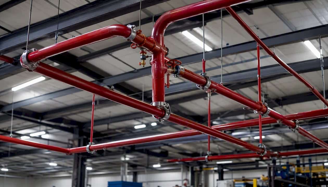
Because water has two paths to any branch takeoff, friction loss in the cross mains drops compared to a tree system of equivalent size. NFPA 13 notes that looped systems provide better hydraulic characteristics than tree systems, though they remain less efficient than a full grid. The practical effect: you can often use smaller cross-main pipe sizes, or serve a larger floor plate from the same supply, compared to a tree layout.
Common applications include:
- Medium-sized office buildings and healthcare facilities where corridors create a natural loop path
- Buildings with multiple risers where tying the cross mains improves redundancy without requiring a full grid
- Facilities where the AHJ or insurer requires a second flow path but the occupancy does not justify grid complexity
- Phased construction where a loop can be extended incrementally as the building grows
The calculation complexity sits between tree and gridded. A simple two-main loop can be balanced with the Hardy Cross method or a basic hydraulic model. When the loop grows to three or more interconnected mains, software becomes the practical choice. The decision between looped and gridded often comes down to one question: does the remote-area demand exceed what the loop can deliver at acceptable pipe sizes? If yes, move to a grid.
Gridded (networked) layout
A gridded system connects parallel cross mains with multiple branch lines running between them. Every branch line receives water from both ends simultaneously, which is the fundamental hydraulic advantage. PHCPPros’ technical overview describes it plainly: gridded systems reduce pressure loss and allow smaller pipe sizes, but they require computer hydraulic programs and careful verification of the most demanding sprinkler combinations.
The hydraulic advantages are real and measurable. Smaller pipe diameters across the system, longer runs from a single supply point, and lower residual pressure demand at the riser are all achievable. AXA XL’s guidance notes that grids permit smaller pipe sizes or longer distances from the supply, but warns that iterative balancing is required and that pipe sizing at conversion points needs careful attention.
Key constraints designers must track:
- Dry pipe systems: Gridded piping is not permitted. Trapped air in a networked grid creates unacceptable delays in water delivery to remote sprinklers.
- Double-interlock preaction systems: Same prohibition. The sequential valve operation combined with a gridded network creates timing and pressure-verification problems that NFPA 13 does not allow.
- Calculation requirement: Every gridded design requires computer hydraulic modeling and iterative verification of the most demanding open-sprinkler combination. Hand calculations are not adequate.
- Best-fit occupancies: Large warehouses, big-box retail, open-plan manufacturing floors, and any building where remote-area distance from the supply would require oversized pipe in a tree or loop arrangement.
How do system operation types restrict layout choices?
The piping arrangement and the system operation type are separate design variables, but they interact in ways that can eliminate options early in concept design. The table below maps each operation type to its permitted layouts and the key constraint to watch.
MeyerFire’s guidance is direct on this point: wet systems are flexible and can use any layout, while dry and preaction systems carry configuration limits tied to trapped air and water-delivery timing. For designers working on pre-action fire sprinkler systems, the layout decision is effectively made before the hydraulic analysis begins — tree or looped, full stop for double-interlock configurations.
Local code amendments occasionally add constraints beyond NFPA 13. Some jurisdictions require AHJ approval for gridded layouts in high-piled storage occupancies, and a few local amendments restrict looped arrangements in certain healthcare occupancies. Always confirm with the authority having jurisdiction before finalizing the layout at concept design.
For fire sprinkler system installations in Colorado, the Denver Fire Department and local AHJs generally follow NFPA 13 without significant amendments to layout rules, but the confirmation step is still worth a phone call before the design progresses.
What calculation method does each layout require?
The calculation complexity scales directly with the number of flow paths in the system.
Tree systems are the only layout where hand calculations remain practical for most projects. With a single flow path, the hydraulic demand at any point is deterministic: sum the flows, apply the Hazen-Williams equation, and work from the remote area back to the supply. Pipe-schedule design, which assigns pipe sizes by table rather than by hydraulic calculation, is also most defensible with tree layouts. For small systems under light hazard, this is a legitimate and code-compliant approach.
Looped systems introduce a second flow path, which means the flow split at each loop junction must be solved simultaneously. The Hardy Cross method handles this for simple two-main loops: assume an initial flow distribution, calculate the head loss around each loop, apply a correction factor, and iterate until the corrections are negligible. It works, but it is tedious for anything beyond two or three loops. AXA XL’s hydraulic guidance references Hardy Cross as the classical balancing method for looped networks, while noting that complex grids make it impractical.
Gridded systems require software. The iterative balancing problem across multiple interconnected branch lines and cross mains cannot be solved reliably by hand for any real-world grid. Programs like HydraCalc, SprinkCALC, or HydraCAD are the accepted tools. The modeling checklist experienced designers follow:
- Set boundary conditions correctly: supply curve from the water authority’s flow test, not a conservative estimate.
- Define nodal assumptions: confirm pipe material, C-factor, and fitting allowances match the specified system.
- Identify the candidate remote areas: do not assume the most distant corner is the worst case — run multiple area positions.
- Verify the hydraulically most demanding combination per NFPA 13 requirements.
- Run at least one supply-degradation sensitivity case: what happens if the residual pressure drops 10 psi from the test value?
- For gridded systems, confirm that the design-area rectangle dimensions comply with NFPA 13. AXA XL uses a longer-side factor of 1.4 × √(area) in its guidance, compared to NFPA 13’s 1.2 × √(area), as a conservative design margin.
Pro Tip: After running your hydraulic model, check mass continuity at every node manually for at least three nodes. If the software’s flow balance is off at any node by more than a rounding error, the model has a setup error — not a hydraulic problem.
How do you choose the right sprinkler layout for your project?
The layout decision is not purely hydraulic. It involves water availability, occupancy, budget, maintenance access, and sometimes seismic or freeze constraints. Work through this checklist in order during concept design.
- Confirm the water supply. Get a current flow test from the water authority. Residual pressure and available flow at the point of connection set the ceiling on what any layout can deliver. A weak supply may force a gridded layout even for a medium-sized building.
- Define the design area and remote-area distance. How far is the most remote sprinkler from the riser? Long runs in a tree layout require large pipe. If the required pipe size becomes impractical or cost-prohibitive, a loop or grid is the answer.
- Identify the occupancy and hazard classification. Light hazard occupancies with modest density can usually be served by a tree layout. Ordinary and extra hazard occupancies with high sprinkler density push toward looped or gridded arrangements to keep pipe sizes manageable.
- Determine the system operation type. As noted above, dry pipe and double-interlock preaction systems eliminate gridded layouts before the hydraulic analysis begins.
- Evaluate installation cost vs. pipe quantity. Gridded systems use more pipe and fittings than tree systems for the same floor area. The hydraulic savings in pipe diameter sometimes offset that cost, but not always. Run a rough material takeoff for both options before committing.
- Consider maintenance and commissioning access. Looped and gridded systems have more isolation points and more complex flushing requirements. In buildings with limited mechanical access or tenant-occupied spaces, that complexity has a real operational cost.
- Check seismic and freeze constraints. In seismic zones, additional bracing requirements apply to all layouts, but gridded systems with more branch-line connections can require more brace points. In freeze-prone areas, gridded wet-pipe systems in unheated spaces create more exposure than a tree layout with fewer dead-leg volumes.
Ask the client and the water authority these specific questions before finalizing the concept:
- What is the current flow test data, and when was it last conducted?
- Are there planned changes to the water distribution system in the next five years?
- Does the AHJ have layout preferences or local amendments beyond NFPA 13?
- What is the contractor’s experience with hydraulic modeling for gridded systems?
Pro Tip: Document every assumption you make at concept design — supply pressure, C-factor, design area position, pipe material. When the final hydraulic model is run six months later by a different engineer, those assumptions are the only thing preventing a complete re-analysis.
Hybrid arrangements and retrofit considerations
Most real projects do not fit cleanly into one layout category. Architects add corridors, tenants change, buildings expand in phases, and the result is usually a hybrid. MeyerFire notes that looped cores with tree branches in individual tenant units are a common pattern in multifamily and mixed-use buildings, where minimizing fire-rated penetrations into units is a priority. Partial gridding adjacent to a riser in a warehouse, with tree branches serving low-hazard office areas, is another standard hybrid.
Retrofit work introduces a specific set of risks that new construction does not face:
- Tie-in point sizing: The existing pipe at the connection point may not be large enough to carry the additional flow a grid or loop requires. Verify the size and condition of existing mains before designing the new layout.
- Pipe sizing at conversion points: Converting a tree section to a partial grid often fails to deliver the expected hydraulic benefit if the small-diameter branch piping near the remote areas is not upsized. PHCPPros’ analysis makes this point directly: those small-diameter runs remain the bottleneck even after the grid connection is made, unless they are replaced.
- Flushing and air removal: A new grid section connected to an existing wet system needs a planned flush sequence. Air trapped in the new piping will create pressure anomalies during commissioning and can mask hydraulic deficiencies.
- Temporary isolation: Plan the isolation valve strategy before work begins. In occupied buildings, the window for system shutdown is often shorter than the work requires, and a staged isolation plan prevents a single long outage.
For sprinkler installation in commercial properties, the retrofit scenario is where the most costly surprises occur. A brief hydraulic sensitivity run on the existing system before design begins will identify whether the supply can support the new layout or whether a supply upgrade needs to be in the project scope.
A practicing designer’s perspective on layout selection
The layout decision gets made twice on most projects: once at concept, informally, based on the designer’s experience and a quick look at the floor plan, and again at final design, formally, after appropriate hydraulic modeling. The gap between those two decisions is where projects get into trouble.
The workflow that actually works starts with site data before any layout preference is formed. Pull the water authority’s flow test, walk the building with the structural drawings, and identify where the risers can go before sketching a layout. A designer who commits to a gridded layout before confirming the supply pressure is setting up a redesign.
Coordination touchpoints that get missed more often than they should: structural penetrations for cross mains in concrete-framed buildings (the structural engineer needs to know early), ceiling obstructions that force branch lines into awkward routing (the architect’s reflected ceiling plan is essential, not optional), and the fire department connection location (which affects riser placement and, in turn, the entire layout geometry).
NICET-certified technicians bring a specific advantage at the field coordination stage. They have seen enough installations to recognize when a layout that looks clean on paper will create access problems during commissioning or maintenance. That field knowledge, combined with hydraulic modeling capability, is what separates a layout that works from one that merely complies.
The honest answer to “which layout is best” is that it depends on the supply, the building, and the operation type — but the designer who runs a quick sensitivity case at concept design and documents the assumptions will spend far less time defending the final design than one who does not.
Preactionfire’s layout design and installation services in Denver
Pre Action Fire has been designing and installing commercial fire sprinkler systems in the Denver Metro Area since 2009. For designers and facility managers who need layout consultation, hydraulic modeling, retrofit installation, or NFPA compliance verification, Preactionfire’s NICET-certified technicians handle the full scope: concept layout selection, computer hydraulic analysis, field installation, commissioning, and post-installation inspection.

The team’s local experience covers wet, dry, and pre-action systems across a range of commercial and industrial occupancies in Colorado. Whether you are selecting a layout for new construction or converting an existing tree system to a partial grid, Preactionfire can run the hydraulic model, identify the pipe-sizing constraints, and manage the installation through final NFPA compliance sign-off. Contact Preactionfire for a layout consultation or site visit.
Sources
The sources below are the primary references for the guidance in this article. Each covers a distinct aspect of sprinkler layout design.
- Understanding Tree, Looped, and Gridded Sprinkler Piping Arrangements
- When to use tree, looped, or gridded systems — MeyerFire
- Sprinkler System Hydraulics (AXA XL Risk Consulting)
- Understanding Sprinkler Piping Arrangements | phcppros